| without support | with support |
PRINCIPLE
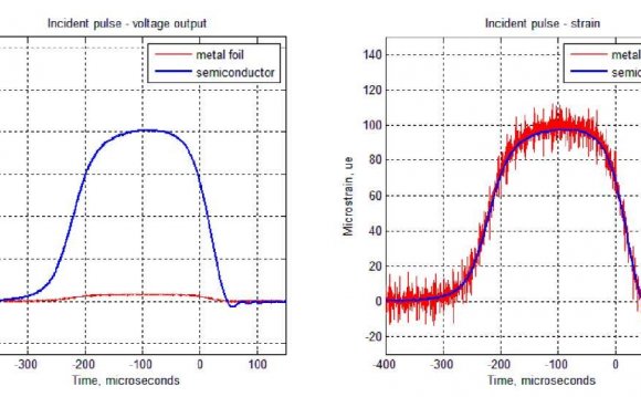
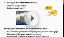
The function of a semiconductor strain gauge essentially consists in a very considerable and accurate change in its electrical resistance with applied mechanical strain. Senzors with these elements give to all mechanisms the ability to respond sensitively to mechanic impulses. They are usually used for force, mass, pressure, torque, acceleration and deformation electric measurements.
The most common use of strain gauges is for half-bridge or full-bridge, because during statical measurements it compensates the temperature effects. Measurement of electric resistance of one strain gauge can be used only there, where we don‘t need to compensate the temperature effects.
| Half-bridge | Full-bridge |
PROPERTIES
Technical merits of semiconductor as compared with wire and foil strain gauges:
- 60x higher strain sensitivit yallowing measurement without amplifiers, with standard ohmmeters, voltmeters and oscilloscopes
- 60x higher threshold sensitivity making possible measurement of strain in metals beginning with a value as low as a millionth of one millimetre per metre
- Small width of strain gauges enabling the design of small and light sensors
- Results of stress analysis of parts that can be subjected to controlled heating are absolutely reliable
- Up to 300°C, monocrystalline silicon strain is without measurable hysteresis Strain gauges made of silicon and gold possess outstanding corrosion resistance
CALIBRATION AND FATIGUE LIFE
Our strain gauges are tested in accordance with procedures of U.S. NAS 942. Each manufactured gauge is cemented to a testing beam and subjected to gradual strain in the range of ±2.5x10⁻³ [m/m] while electrical resistance is simultaneously measured. Strain gauges with a damaged active surface structure fail under tensile strain +2.5x10⁻³ [m/m]. Gauges unimpaired by the tensile test are taken off the test beam and their temperature dependence of resistance is determined. The computer then calculates constants of the strain equation from the dependence of resistance on strain. Minimal tolerance of characteristics is achieved by measurements of each gauge and responsible selection. The dependence of strain sensitivity on temperature is determined for each type and statistically checked.
Fatigue life of silicon strain gauges is better than that of metallic strain gauges. The Aeronautical Research and Test Institute in Prague has made use of our silicon strain gauges to run extensive tests on the fatigue life of turbine and compressor vanes of aircraft, which is represented by the following curve.
Fatigue life of silicon strain gauges is better than fatigue life of compressor and turbine vanes (curve) stressed under applied symmetrical dynamic strain
Strain gauges were cemented to blades of martensitic stainless steel and nickel alloy Nimonic 95 with commercial adhesive PT-5 cured at 210°C/2h. Blades vibrated on their own frequency of 1.5kHz to 6 kHz in the test, their strain was set up and controlled according to gauge signals. Tests always ended with vane rupture, strain gauges performed without failure.
CODE DESIGNATION AND DIMENSIONS
At present, we have these types of strain gauges in stock: Type „Positive“, length 1.5mm, 3mm and 6mm, with gauge factor C1 = 120 - 150 and with electrical resistance 120, 350 and 1000 Ohm. Of course, we are able to produce strain gauges with parameters according to customer's requirements.
We deliver semicoductor strain gauges in two sorts of tolerance at pack, specified by assurance of their tolerance characteristics. For dynamic measurement and stable temperatures are suitable strain gauges marked as N-sort. For static measurements, sensors and strain gauges for temperature fluctuation are suitable ones marked as T-sort.
| Tolerance at pack
(standard is 5 pieces) |
Tolerance of typ | |||
|---|---|---|---|---|
| N-sort | T-sort | |||
| R0 - Electrical resistance of the free gauge | ± 0.4% | ± 0.25% | ± 5% | ± 3% |
| RB - Electrical resistance of the free gauge with support | ± 1% | ± 0.50% | ± 10% | |
| C1 - (Gauge factor) | ± 2% | |||
| C2 | ± 8% | according to contract | ||
| α - Temperature resistance coefficient of the free gauge | ± 0.02%/°C | |||
| Positiv limit static tensile strain | 0.3% | |||
RELATED VIDEO


Share this Post
latest post
-
 Semiconductor Processing November 26, 2023
 -
 Top Fabless Semiconductor companies October 27, 2023
 -
 Silicon Valley Semiconductor companies September 27, 2023
 -
 New Semiconductor companies August 28, 2023
 -
 List of Semiconductor companies in USA July 29, 2023
 -
 Semiconductor properties June 29, 2023
 -
 Semiconductor industry companies May 30, 2023
 -
 Canadian Semiconductor company April 30, 2023
 -
 Semiconductor companies in Europe March 31, 2023
 -
 Semiconductor jobs in Europe March 1, 2023
 -
 Freescale Semiconductor, Ltd January 30, 2023
 -
 Freescale Semiconductor Patent December 31, 2022
 -
 Freescale Semiconductor news December 1, 2022
 -
 Freescale Semiconductor stock symbol November 1, 2022
 -
 Global Semiconductor company October 28, 2022