 The Structures, Electronic Symbols, Basic Operations and Several Characteristics Representations of Power Semiconductor Devices
Recommended Level
Beginner
Introduction
This technical article is dedicated to the review of the following power electronics devices which act as solid-state switches in the circuits. They act as a switch without any mechanical movement.
- Power Diodes
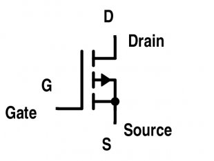
- Metal-Oxide-Semiconductor Field-Effect Transistor (MOSFET)
- Bipolar -Junction Transistor (BJT)
- Insulated-Gate Bipolar Transistor (IGBT)
- Thyristors (SCR, GTO, MCT)
Solid-state devices are completely made from a solid material and their flow of charges is confined within this solid material. This name “solid state” is often used to show a difference with the earlier technologies of vacuum and gas-discharge tube devices; and also to exclude the conventional electro-mechanical devices (relays, switches, hard drives and other devices with moving parts).
The transistor by Bell Labs in 1947 was the first solid-state device to come into commercial use later in the 1960s. In this article, similar solid-state devices such as power diode, power transistor, MOSFET, thyristor and its two-transistor model, triac, gate turn-off thyristor (GTO), insulated-gate bipolar transistor (IGBT) and their characteristics (such as i-v characteristics and turn-off characteristics) is also presented. In power electronics circuitry, these switches act in saturation region and work in linear region in the analog circuitry such as in power amplifiers and linear regulators. This makes these switches highly efficient since there are lesser losses during the power processing.
A. Power Diode
A power diode has a P-I-N structure as compared to the signal diode having a P-N structure. Here, I (in P-I-N) stands for intrinsic semiconductor layer to bear the high-level reverse voltage as compared to the signal diode (n-, drift region layer shown in Fig. 2). However, the drawback of this intrinsic layer is that it adds noticeable resistance during forward-biased condition. Thus, power diode requires a proper cooling arrangement for handling large power dissipation. Power diodes are used in numerous applications including rectifier, voltage clamper, voltage multiplier and etc. Power diode symbol is the same as of the signal diode as shown in Fig.1.
Figure 1. Symbol for Power Diode
Figure 2. Structure of Power Diode
Other features that are incorporated in the power diode letting it handle larger power are:
(a) Use of guard rings
(b) Coating of Silicon Dioxide layer
Guard rings are of p-type that prevents their depletion layer merge with the depletion layer of the reverse-biased p-n junction. The guard rings prevent the radius of the curvature of the depletion layer boundary to become too narrow which increases the breakdown strength. Coating of SiO2 layer helps in limiting the electric field at the surface of the power diode.
If thickness of lightly doped I layer (n- layer) > depletion layer width at breakdown ⇒ Non-punch through power diode.
(This means depletion layer has not punched through the lightly-doped n-layer.)
If thickness of I layer < depletion layer width at breakdown ⇒ Punch through power diode.
Characteristics of Power Diode
The two types of characteristics of a power diode are shown in Fig. 3 and Fig. 4 named as follows:
(i) Amp-volt characteristics (i-v characteristics)
(ii) Turn-off characteristics (or reverse-recovery characteristics)
Figure 3. Amp-Volt Characteristics of Power Diode
Cut-in voltage is the value of the minimum voltage for VA (anode voltage) to make the diode works in forward conducting mode. Cut-in voltage of signal diode is 0.7 V while in power diode it is 1 V. So, its typical forward conduction drop is larger. Under forward-bias condition, signal diode current increases exponentially and then increases linearly. In the case of the power diode, it almost increases linearly with the applied voltage as all the layers of P-I-N remain saturated with minority carriers under forward bias. Thus, a high value of current produces results in voltage drop which mask the exponential part of the curve. In reverse-bias condition, small leakage current flows due to minority carriers until the avalanche breakdown appears as shown in Fig. 3.
Figure 4. Turn-Off Characteristics of Power Diode: a) Variation of Forward Current if ; b) Variation of Forward Voltage Drop vf ; c) Variation of Power Loss
After the forward diode comes to null, the diode continues to conduct in the opposite direction because of the presence of stored charges in the depletion layer and the p or n-layer. The diode current flows for a reverse-recovery time trr. It is the time between the instant forward diode current becomes zero and the instant reverse-recovery current decays to 25 % of its reverse maximum value.
Time Ta : Charges stored in the depletion layer removed.
Time Tb : Charges from the semiconductor layer is removed.
Shaded area in Fig 4.a represents stored charges QR which must be removed during reverse-recovery time trr.
Power loss across diode = vf * if (shown in Fig. 4.c)
As shown, major power loss in the diode occurs during the period tb.
Recovery can be abrupt or smooth as shown in Fig. 5. To know it quantitatively, we can use the S – factor.
Ratio Tb/Ta : Softness factor or S-factor.
S-factor: measure of the voltage transient that occurs during the time the diode recovers.
S-factor = 1 ⇒ low oscillatory reverse-recovery process. (Soft –recovery diode)
S-factor t1, gate-to-source voltage is constant. Thus, the entire current is now being drawn from CGD. Up to time t3, the drain current will almost reach zero value; which turns off the MOSFET. This time is known as the fall time, this is when the input capacitance discharges up to the threshold value. Beyond t3, gate voltage decreases exponentially to zero until the gate current becomes zero.
RELATED VIDEO


RELATED FACTS
-
 Multi-junction solar cells or tandem cells are solar cells containing several p-n junctions. Each junction is tuned to a different wavelength of light, reducing one of the largest inherent sources of losses, and thereby increasing efficiency. Traditional...
-
 The grown-junction transistor was the first type of bipolar junction transistor made. It was invented by William Shockley at Bell Labs on June 23, 1948 (patent filed June 26, 1948), six months after the first bipolar point-contact transistor. The first germanium...
- The purpose of this article is to summarize the methods used to experimentally characterize a semiconductor material or device (PN junction, Schottky diode, etc.). Some examples of semiconductor quantities that could be characterized include depletion width, carrier...
Share this Post
latest post
-
 Semiconductor Processing November 26, 2023
 -
 Top Fabless Semiconductor companies October 27, 2023
 -
 Silicon Valley Semiconductor companies September 27, 2023
 -
 New Semiconductor companies August 28, 2023
 -
 List of Semiconductor companies in USA July 29, 2023
 -
 Semiconductor properties June 29, 2023
 -
 Semiconductor industry companies May 30, 2023
 -
 Canadian Semiconductor company April 30, 2023
 -
 Semiconductor companies in Europe March 31, 2023
 -
 Semiconductor jobs in Europe March 1, 2023
 -
 Freescale Semiconductor, Ltd January 30, 2023
 -
 Freescale Semiconductor Patent December 31, 2022
 -
 Freescale Semiconductor news December 1, 2022
 -
 Freescale Semiconductor stock symbol November 1, 2022
 -
 Global Semiconductor company October 28, 2022